| General Information | |
| fluid type | air |
| density | 1.293 kg/m3 |
| Viscosity | 1.75 E-5 kg/m-s |
| Operational Pressure | 101325 Pa |
| No | General Step | Details of Step | Notes |
| 1 | Pre-Proccessor | first analysis | analysis about problem case. at this time the case is about flow characteristic on CG Stocker's Boiler. predict about flow distribution on the furnance, with some parameters. its a weight of boiler (distance from air inlet and outlet), inlet velocity, operational pressure |
| prediction | with those parameters, we can predict about air flow characteristic on the inside of CG Stocker's Boiler. if inlet velocity is about the same or approach to the weight value, the flow characteristic is shaping a layer looks like a membran on the midle (at the line of inlet side) and not permeating on the wall of model. but if the inlet velocity is lower than the weight value. the result of flow characteristic will be sphread inside the boiler. | ||
| input | starting tools | start to using software (cfdsof) with login to remote desktop connections to the address vortex.cfdsof.com . you must have an cfdsof account to login on this connection | |
| open the program | klick icon on the desktop which is a cfdsof simulation programs shortcut on the desktop. | ||
| start use the programs | start using this programs. input all needed data. like a density, viscosity, operation pressure to get the result value | ||
| data input | input all needed data for simulation. its a velocity (variable value canging), wieght geometry canging. a variant for a variable weight, I choosen a from 5m to 15m with 5m gap., and velocity variant for that project is 0.5,1,2,4 m/s | ||
| 2 | proccessor | itereation | its about boundary condition calculation. mesh live cell calculate |
| 3 | Post-Proccessor | contour result | |
| velocity magnitude contour | v1=4m/s v2=2m/s h=10m  v1=4m/s v2=2m/s h=15m 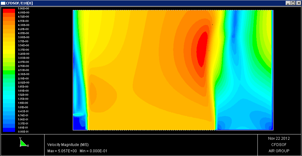 v1=0.5m/s v2=2m/s h=15m  v1=1m/s v2=2m/s h=15m  v1=2m/s v2=2m/s h=15m  |
With the simulation result above. We can explain about characteristic of flow distribution of air in the inside of the models. As an expectation, air flow pattern shaping a line (high gradien) at the line straight of end the inlet side and start to spread. If the height is higher, air flow would be fully developed. At this case, models have an another inlet, cause this condition air flows will be disturbed. Hence the inlet air flow vector increas (at the red contour). And why the pattern occurs there is a high speed on the right side is due to the accumulation of value due to the velocity vector of the flow coming from the left side earlier. If the entry speed is reduced will see a crate aka flow distribution patterns with speed 0.5 and 1 m / s. the pattern looks airflow distribution began to spread up the walls in the model. Indicates the farther side of the inlet to the outlet side of the face (there are no bends, etc.), then the flow will be more spread out and more fully extended (fully develope condition). The condition of the inlet-outlet spacing ratio at speeds not approaching a value of 1. From of flow distribution patterns as the pressure distribution pattern will be visible. Meeting points in two or more vectors stagnation, where the pressure just before the point of the meeting was low and right at the meeting point will be high pressure, resulting from the momentum going at that point. |
Tidak ada komentar:
Posting Komentar